Note
Go to the end to download the full example code.
Importing a CAD model#
Not every model is drawn in Magnelio. A connector, a housing, a machined part — anything with a mechanical drawing behind it — already exists in a CAD system, and rebuilding it with primitives is both work and a source of discrepancies between the simulated and the manufactured part.
This tutorial imports such a part from a STEP file, gives its solids
materials, and runs it: a coaxial feed-through, drawn in millimetres,
that comes out as a 50 ohm line whose transmission can be checked
against the closed form. The file connector.step sits next to this
script.
from pathlib import Path

import matplotlib.pyplot as plt
import numpy as np

import magnelio as mio
from magnelio import plots, ports
from magnelio.constants import *
from magnelio.io import import_step

# The STEP file sits next to this script, or in the working directory.
HERE = Path(__file__).parent if "__file__" in globals() else Path.cwd()
STEP_FILE = HERE / "connector.step"
Looking inside the file#
Import first, ask questions later: called without materials,
import_step() returns everything the file
contains. The result is a Group, and
members() walks its solids.
Two things are worth noting in the output. The names are the ones the part carries in the CAD system — they are the handle everything else hangs on. And the sizes are in meters although the file was drawn in millimetres: STEP states its own unit, and the import converts.
parts = import_step(STEP_FILE)

for solid in parts.members():
    low, high = solid.bounding_box()
    size = tuple(round(h - lo, 5) for lo, h in zip(low, high))
    print(f"{solid.name:<12} {size} m")
centre_pin   (0.0013, 0.0013, 0.012) m
insulator    (0.00436, 0.00436, 0.012) m
outer_shell  (0.007, 0.007, 0.012) m
Materials come from you, not from the file#
A CAD system stores a material as a name for a parts list. A field solver needs permittivity, permeability and conductivity, and no exchange format carries those — so materials are assigned on import, keyed by the solid names just printed.
Names are what a re-export preserves, so this mapping keeps working after the drawing changes; positions and face counts do not.
ptfe = mio.Material(name="PTFE", epsilon=(2.1,) * 3, color=(0.45, 0.68, 0.84), alpha=0.6)

connector = import_step(
    STEP_FILE,
    {
        "centre_pin": "pec",
        "outer_shell": "pec",
        "insulator": ptfe,
    },
)
A key that matches nothing is an error rather than a silent no-op,
and a solid that no key matched arrives without a material — a
construction body, usable as a Boolean operand but refused by
add(). A half-mapped assembly cannot
quietly mesh as vacuum.
For an assembly with many similarly named parts, wildcards do the grouping, and a literal name overrules them:
import_step("housing.step", {"*": aluminium, "window": ptfe})
The imported solids are ordinary geometry#
What comes back are shapes like any other: they have a volume, take Boolean operations and the chainable verbs, and go into a model. Everything outside them is the model’s background — here metal, which closes the coaxial line off at the outside.
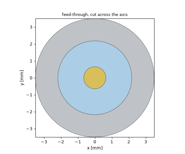
The brass of the pin and the steel of the shell are the colours the CAD system painted those parts with: STEP carries them, and the import hands them on. They are decoration only — the physics comes from the materials assigned above.
The insulator shows the other half of the rule, and why a material
may want a colour of its own. CAD systems paint PTFE off-white, and
an off-white ring between two greys is a picture that says nothing
about what the parts are. A color on the material overrules
the file, so the dielectric above was given the tint Magnelio would
have chosen for it anyway, and reads as a dielectric again. Neither
color nor alpha touches the field solve.
Running the imported part#
From here on nothing is specific to the import. The line is coaxial with a 0.65 mm pin in a 2.18 mm bore filled with PTFE, so both ends take an analytical coax port, and a single run gives the S-matrix.
R_IN, R_OUT, EPS_R = 0.65e-3, 2.18e-3, 2.1
LENGTH = 12e-3
f_max = 15e9

for name, plane in (("port1", "zmin"), ("port2", "zmax")):
    model.add_port(
        ports.PortAnalytical(
            name=name,
            plane=plane,
            family="coax",
            inner_radius=R_IN,
            outer_radius=R_OUT,
            epsilon_r=EPS_R,
        )
    )

mesh = mio.Mesh.from_geometry(model, mio.MeshControl(max_cell_size=0.25e-3), f_max=f_max)
print(f"grid: {mesh.Nx} x {mesh.Ny} x {mesh.Nz} cells")

analysis = mio.AnalysisScatteringTD(mesh=mesh, verbose=False)
result = analysis.run()
  mesh | feature planes
  mesh | grid lines
  mesh | materials
  mesh | conformal cells
  mesh | PEC masks
  mesh | 32 x 32 x 48 cells
grid: 32 x 32 x 48 cells
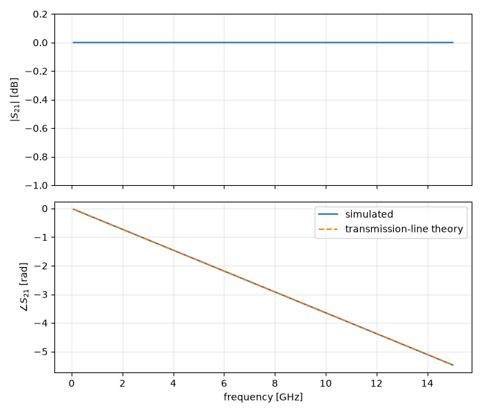
A uniform, lossless line transmits everything and delays it by the time the wave needs to cross — so the check is the phase of \(S_{21}\):
f = result.f_axis
s21 = result.S("port2", "port1")
expected = -2 * np.pi * f * np.sqrt(EPS_R) * LENGTH / C0

fig, (ax_mag, ax_phase) = plt.subplots(2, 1, figsize=(7, 6), sharex=True)
ax_mag.plot(f * 1e-9, 20 * np.log10(np.abs(s21)))
ax_mag.set_ylabel(r"$|S_{21}|$ [dB]")
ax_mag.set_ylim(-1.0, 0.2)
ax_mag.grid(True, alpha=0.3)

ax_phase.plot(f * 1e-9, np.unwrap(np.angle(s21)), label="simulated")
ax_phase.plot(f * 1e-9, expected, "--", label="transmission-line theory")
ax_phase.set_xlabel("frequency [GHz]")
ax_phase.set_ylabel(r"$\angle S_{21}$ [rad]")
ax_phase.legend()
ax_phase.grid(True, alpha=0.3)
fig.tight_layout()
Units, healing, and the other format#
Three things are worth remembering beyond this example.
The unit is the one risk that is silent. STEP states it, so
import_step is safe. .brep files — the geometry kernel’s own
dump — do not, which is why
import_brep() insists on being told:
part = import_brep("horn.brep", unit="mm", material="pec")
Files travel between kernels, and not always intact. Every solid
is repaired on import; if one is still invalid afterwards the import
says so and names it. unify=True additionally merges the
neighbouring faces that exporters like to split a plane into.
Only solids are imported. A material fills a volume, so surface bodies are reported and skipped — stitch them into solids in the CAD system first.
Total running time of the script: (0 minutes 2.667 seconds)